Wear rarely appears as a dramatic break. More often, it starts as a faint groove on a shaft, a rough bearing sound, a small oil leak, or uneven tire wear. These clues can be easy to miss during a quick inspection. They may also point to different causes, such as poor lubrication, contamination, misalignment, excessive load, or ordinary aging.
Knowing how to identify wear signs in mechanical and auto parts helps owners and technicians spot changes before they become larger problems. Look closely at the part’s surface, movement, temperature, noise, and fit. A polished contact patch, metal dust near a joint, cracked rubber, or a fastener that repeatedly loosens deserves attention. Small details matter.
Not every mark means a part has failed. That judgment is not always neat. Compare the condition with the manufacturer’s service guidance, maintenance history, and the part’s normal operating environment. Clean the area before inspecting it, use suitable lighting, and record what you observe. Photos can make gradual changes easier to compare.
This guide explains common wear patterns across mechanical and automotive components, from bearings and belts to brake parts and suspension joints. It also covers practical inspection methods and signs that call for professional assessment. If a safety-critical component shows damage, unusual play, or uncertain condition, avoid guessing. A qualified technician can determine whether repair or replacement is needed. Good inspection is useful, but it cannot replace proper measurement or hands-on diagnosis.
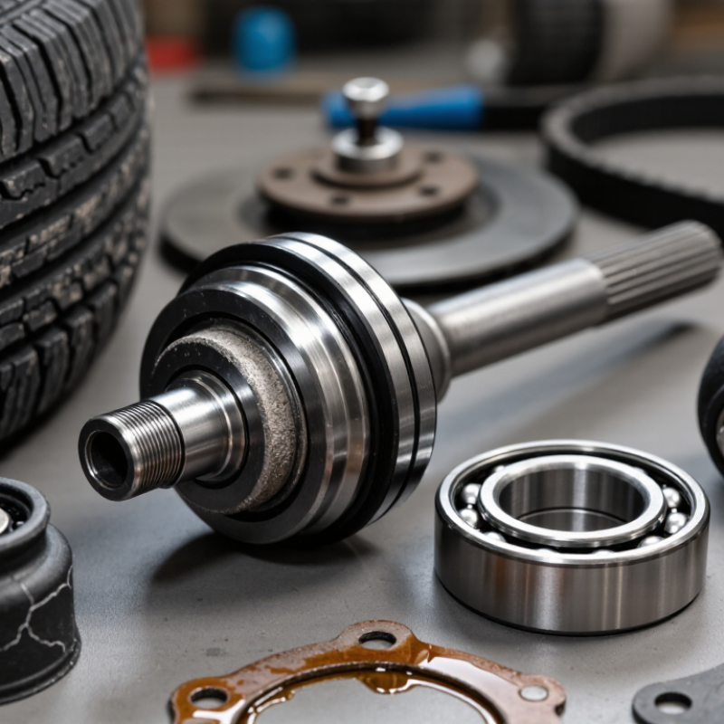
Wear in mechanical and automotive parts rarely has one appearance. Abrasive wear leaves parallel grooves when grit or metal particles cross a surface. On a shaft or gear tooth, these lines may follow the direction of motion. Adhesive wear looks different: transferred metal, scoring, or a smeared, dark patch can indicate rubbing under poor lubrication. Small clues matter. Color alone is not a diagnosis; heat, oil condition, and operating load can change the mark.
Fatigue wear often begins as tiny pits or flakes on rolling bearings and gear teeth. Repeated contact stress breaks away material, even when parts look clean between inspections. Fretting creates reddish-brown or black debris where lightly moving joints meet, such as a hub fit or bolted connection. Corrosive wear may appear as dull etching, rust, or uneven material loss. Erosion often leaves directional grooves caused by fast-moving fluid or particles. Compare both sides, check clearances, and note where debris collects. A photograph helps. Mixed wear is common, and a damaged part may be the result rather than the original cause. Check lubrication, alignment, contamination, and temperature before replacing components.
Surface changes can reveal how a mechanical or automotive part has been working. Look for scoring: fine, parallel grooves that may suggest abrasive debris or poor lubrication. Pitting appears as small cavities, often clustered around contact areas. A polished strip can indicate repeated rubbing, while blue or brown discoloration may point to excess heat. Cracks, flaking, and uneven edges deserve close attention. Small marks matter.
Tips: Wipe away loose dirt with a suitable cloth, then inspect the part under bright, angled light. Compare similar surfaces, such as both sides of a bearing or adjacent gear teeth. Check for sharp burrs, embedded particles, or wear concentrated on one edge. Never inspect a hot or moving assembly.
Appearance alone cannot confirm the cause. A scratch may come from handling, and dark residue may be ordinary buildup rather than damage. It is easy to overread a faint mark. Record where the change appears, then compare it with the part’s service limits or have a qualified technician measure it. A visual check is useful, but it is not a substitute for measurement.
How to Identify Wear Signs in Mechanical and Auto Parts?
Park the vehicle or stop the machine, let hot parts cool, and make moving components safe before inspection. Wipe away loose grease and dust with a clean cloth; grime can hide fine cracks. Use a bright flashlight and inspect surfaces from several angles. Look for scoring, pitting, rust, discoloration, and edges that appear rounded or chipped. Check for unusual looseness by gently moving the component by hand. Don’t force it. On shafts and bearings, feel for rough spots or play, then compare measurements with the service specification. A ruler is not precise enough for close tolerances. Take clear photos and note where each mark appears.
For auto parts, inspect tires for uneven tread, sidewall bulges, and embedded debris. Check belts for fraying or glazing, and examine hoses for swelling, leaks, or cracks near their clamps. Look at brake components for uneven wear, deep grooves, or fluid traces; leave uncertain brake issues to a qualified technician. Compare wear across matching parts, such as both sides of an axle. One worn edge may point to alignment, lubrication, or load problems rather than a faulty part alone. Patterns matter. Record the date, location, and measurement, then recheck after use. A quick visual check can miss internal damage, so treat unusual noise, heat, or vibration as a reason for a closer inspection.
Measuring wear means comparing a part with its documented limits, not judging by appearance alone. Start with the drawing or service specification: record the permitted diameter, clearance, runout, or surface condition. Clean the part, let it reach a stable temperature, then use a calibrated micrometer, bore gauge, or dial indicator. Small details matter. A burr can distort a reading, and measuring at only one point can hide uneven wear. Take readings at several positions and note the instrument’s resolution and measurement uncertainty. I would not treat a borderline result as a confident pass; repeat it and document the conditions.
For a bearing journal, for example, measure at multiple angles and along its length, then compare the smallest and largest readings with the specified tolerance. For a brake component, use the manufacturer’s minimum-thickness limit rather than a visual estimate. The U.S. Department of Energy’s Operations & Maintenance Best Practices Guide reports that predictive maintenance programs have achieved 25–30% lower maintenance costs and 70–75% fewer breakdowns. These are reported program outcomes, not guaranteed results for every workshop. Still, consistent measurements help reveal trends before a part crosses its limit. Record the date, location, tool, and result. Easy to overlook. A rushed measurement, or an unclear specification, can make good data misleading.
The readings below are illustrative inspection examples, not universal service limits. Compare measurements with the specifications for the exact part and application; replace or service parts according to the applicable manual and local requirements.
| Part | Common Wear Signs | How to Measure | Example Finding | Specification Comparison | Example Assessment |
|---|---|---|---|---|---|
| Brake rotor | Scoring, heat spots, cracks, vibration, or thickness below the marked minimum | Measure thickness at several points around the braking surface using a micrometer; check the rotor marking or service specification. | Minimum thickness marked on rotor: 24.0 mm; measured thickness: 23.7 mm | Measured thickness is 0.3 mm below the specified minimum. | Below limit — replace |
| Brake pads | Thin friction material, uneven wear, cracking, or a pad-wear indicator contacting the rotor | Measure the friction material only, excluding the backing plate, with a ruler or caliper. | Friction material: 2.5 mm; applicable service guidance calls for replacement at 3.0 mm. | Measured thickness is below the stated replacement threshold. | Replace; inspect caliper and rotor |
| Passenger-vehicle tire | Shallow tread, uneven wear, exposed cords, bulges, or cuts | Use a tread-depth gauge in the main grooves at multiple points across the tire and around its circumference. | Lowest measured tread depth: 2.0 mm | Below the commonly cited 1.6 mm (2/32 in) threshold in some jurisdictions; legal requirements vary. | Near end of service life; check local rules |
| Engine cylinder bore | Scuffing, a pronounced ridge, scoring, or excessive taper and out-of-round wear | Measure with a dial bore gauge at several heights and in two perpendicular directions; compare results with the engine specification. | Example measurements: 86.02 mm and 86.08 mm at the same height, in perpendicular directions. | Difference between readings is 0.06 mm; acceptability depends on the specified bore and out-of-round limit. | Compare all readings with the engine specification |
| Drive belt | Cracks, missing ribs, frayed edges, glazing, or persistent squealing | Inspect the full belt length with the engine off; check tension or deflection using the method specified for the belt system. | Several ribs are cracked and one edge is frayed. | Visible damage is present; replacement criteria and tension limits are system-specific. | Replace and inspect pulleys |
| Ball bearing | Roughness, noise, heat, discoloration, pitting, or excessive radial movement | Rotate by hand and measure radial or axial movement with a dial indicator using the prescribed test setup. | Measured radial movement: 0.12 mm; bearing feels rough during rotation. | Compare measured clearance with the bearing or machine specification; roughness is also a warning sign. | Investigate; replace if outside limits or damaged |
| Shaft journal | Scoring, grooves, discoloration, reduced diameter, or excessive bearing clearance | Measure journal diameter at multiple positions and directions with a micrometer; calculate taper and out-of-round. | Diameter readings range from 39.96 mm to 39.99 mm. | Compare the smallest diameter and calculated variation with the shaft and bearing specifications. | Check limits and mating-part clearance |
| Hydraulic cylinder rod | Scoring, pitting, corrosion, chrome flaking, or fluid leakage past the seal | Clean and inspect the rod; measure diameter and runout with suitable precision tools. | Visible pitting is present in the seal travel area. | Surface damage in the seal path can damage seals; allowable finish and runout depend on the cylinder specification. | Repair or replace; inspect the seal |
Assess wear severity by comparing measured condition with the part’s service limits, not appearance alone. A groove that catches a fingernail, blue heat discoloration, metal flakes in lubricant, or growing shaft play can signal more than cosmetic damage. Record dimensions with a micrometer or dial indicator, photograph the defect, and note noise, temperature, leakage, and operating hours. Small changes matter. A clean-looking surface can still hide fatigue cracks or internal bearing damage.
Repair may be reasonable when wear is localized and the part remains within its specified limits. Replace or escalate inspection when cracks, severe pitting, loose fits, repeated overheating, or rapidly increasing vibration appear. Check the cause, too: misalignment, contamination, poor lubrication, or excess load can ruin a repaired part again. For vehicle components, follow the applicable service procedure; do not rely on visual judgment for brakes, steering, or other safety-critical systems.
The U.S. Department of Energy’s Operations & Maintenance Best Practices Guide, Release 3.0 (2010), reports potential maintenance-cost reductions of 25–30% and breakdown reductions of 70–75% for predictive maintenance programs. Those are program-level estimates, not guarantees for every workshop. That distinction matters. A single worn component may need replacement even when the overall maintenance data look favorable.
It often leaves parallel grooves on shafts or gear teeth. Grit may travel along the direction of motion.
Look for transferred metal, scoring, or a dark smeared patch. Poor lubrication can contribute, but the mark alone cannot confirm the cause.
They may indicate fatigue from repeated contact stress. Flaking can appear too. A clean surface does not rule out hidden damage.
Wipe off loose dirt and use bright, angled light. Compare similar surfaces and look for burrs, embedded particles, or uneven wear. Never inspect a hot or moving assembly.
Blue or brown areas may point to excess heat. Oil condition and operating load also matter. Color alone is not a diagnosis.
Compare measurements with the part’s service limits. A micrometer or dial indicator can help. Record noise, temperature, leakage, and operating hours.
Cracks, severe pitting, loose fits, repeated overheating, or rising vibration deserve attention. A groove that catches a fingernail may also be significant.
Misalignment, contamination, poor lubrication, or excess load can damage a repaired part again. The worn part may not be the original cause.
No. Appearance can mislead, and faint marks are easy to overread. Use measurements, and follow qualified service procedures for safety-critical parts.
How to identify wear signs in mechanical and auto parts begins with understanding common wear patterns, such as abrasion, corrosion, pitting, cracking, deformation, and uneven contact. Inspect each part under good lighting, looking for changes in color, texture, shape, or surface finish. Pay special attention to grooves, edges, joints, and areas that experience repeated friction or pressure. A careful, step-by-step inspection helps distinguish normal surface marks from damage that may affect how a part works.
Next, measure worn areas using suitable tools and compare the results with the part’s specifications or service limits. Consider the location, depth, and extent of the wear, along with any effect on fit, movement, or performance. This assessment helps determine whether a part can remain in service, needs repair, or should be replaced. Recording findings and checking related components can also help reveal the cause of wear and prevent further damage.

Xinli Technology